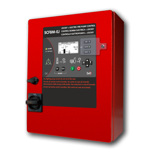
Star Delta Controllers electric fire pumps EN 17451 / EN 12845, LPC TB210, UNI 10779
SCF8M-E-U Star-delta Starting Fire Pump Controllers monitor, display and record Fire Pumps systems information. They are designed to meet and exceed the requirements of the EN 12845 and LPC TB210 standards.
SCF830M-E-U controllers are high specification instruments and apply the most advanced technology in the starting and stopping process of Electric Fire Pumps. They protect the Fire Pumps through the action of the alarms both connected and generated by the controllers themselves; They manage the communication with the operator and with both the contour elements and the remote manned centre.
MAIN FEATURES: SCF8M-E-U
Electric Fire Pumps controllers: EN 17451 / EN 12845, LPC TB210, UNI 10779
Nº STANDARDS & TECHNICAL RULES 1 Standard EN 17451:2024 / EN 12845: 2016 2 Standard UNE 23500 Ed.2018 3 Standard UNI 10779 Ed. 2014 4 Standard IEC 61439-1 Ed. 2011 Low-voltage switchgear and controlgear assemblies 5 Tech. Rule CEPREVEN R.T.1-ROC Ed.2004 6 Tech. Rule CEPREVEN R.T.2-ABA Ed.2006 Nº RANGE OF MODELS (according to type plate) 1 Incoming line voltage 400 VAC / 230 VAC 2 Mains frequency 50Hz / 60 Hz. 3 Main pump motor size Standard up to 200 kW 4 Jockey pump motor size Up to 5,5 kW 5 Motor starter type DOL / λ-Δ according to the motor power Nº CONSTRUCTIVE FEATURES 1 External enclosure IP65 Protected from total dust ingress (NEMA 4) 2 Impact rating: IK10 (except for display) 3 Fireproof grade: Fire extinguishes <30s 4 Display Transflective: Visible under direct sunlight 5 Wiring Halogen free 6 Fireproof: RZ1 according to EN50200 (830ºC for 90min) 7 Pump room temperature 20 ºF to 122ºF (-5ºC to 55ºC) 8 Isolation rating between phases 500 VAC 9 Isolation rating between phases and ground 2.500 VAC 10 Isolation impedance between phases and ground 2 MΩ 11 Earthing system TT system (neutral and earht connected separatelly ) 12 Electromagnetic environment CEM-1 Nº MEASURING INSTRUMENTS IN THE DISPLAY 1 System 3 Voltmeter: voltage for every phase L1-L2-L3 (RMS) 2 1 Mains frequency meter 3 1 pump rotation/phase rotation 4 1 Manometer pump discharge pressure ( pressure sensor required with 4-20 mA signal) 5 Main pump 1 Ammeter: pump current (RMS) 6 1 active power in KW (RMS) 7 1 Power factor (Cos φ) 8 1 Flowmeter: (flow sender required with 4-20 mA signal) 9 Jockey pump 1 Ammeter: pump current (RMS) 10 1 Active power in KW (RMS) 11 1 Power factor (Cos φ) 12 Controller 1 Voltmeter: Internal voltage 13 Controller 1 Voltmeter: back-up battery voltaje Nº PUMS & SYSTEM PROTECTION 1 Voltage loss 2 Normal power phase reversal 3 Normal frequency loss 4 Main pump protection trip 5 Overload main pump 6 Fail to start main pump 7 Jockey pump protection trip 8 Controller power loss 9 Low water reservoir tank 10 Low priming tank level 11 Low back-up battery voltage 12 Main pump pressure switch short circuit 13 Main pump pressure switch open circuit 14 Low power factor main pump 15 Low power factor jockey pump 16 Under-current main pump 17 Under-current Jockey pump 18 Overload Jockey pump 19 Pressure sensor fault Nº COMMUNICATIONS & SIGNAL TRANSMISSION 1 micro USB Port Boot loader for firmware upgrading 2 SAF8M (control panel PLC ) configuration 3 PC monitoring: Pump and installation general condition 4 Pendrive data down-load: Events historical / Pressures historical 5 ETHERNET (Optional) SAF8M (control panel PLC ) configuration 6 PC monitoring: Pump and installation general condition 7 RS485 port (Optional) SAF8M (control panel PLC ) configuration 8 PC monitoring: Pump and installation general condition 9 Voltage free contacts :
up to 30 V DC / 0,3 AVoltage loss 10 Main pump automatic mode OFF 11 Fail to start / not discharge pressure 12 Grouped alarmas 13 Pump on demand 14 Pump running with pressure Nº LANGUAGES / OTHER FEATURES 1 ENGLISH / ESPAÑOL / ITALIANO / FRANÇAIS / PORTUGUES /DEUTSCH / NEDERLANDS 2 State of pressure switches: Short-circuit / Open circuit monitoring 3 System pressure meter: Value displayed on digital screen. Selection of demand and stop levels 4 3 operatin modes: OFF/ MAN / AUTO: Keylock for AUTOMATIC mode 5 Events log: Historical of 500 events in memory: Downloadable to pendrive 6 Pressures register: Historical of 16,000 records in memory: Downloadable to pendrive 7 Pump test: Historical of 50 records in memory: Downloadable to pendrive 8 Main pump working hours + Jockey pump start count & hours 9 Digital & Analog Input / Output test on display 10 Power elements: Contact breakers in AC-3 / Isolator switches in AC-23


