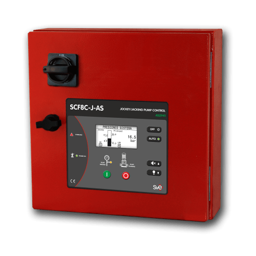
SCF8C-J-AS. Control para bombas Jacking según la norma australiana AS 2941
SCF8C-J-AS son instrumentos completos, de uso sencillo, automáticos y configurables, útiles para la gestión del funcionamiento de bombas Jacking hasta 7,5 kW entornos con circunstancias diversas.
Los controladores SCF8C-J-AS gobiernan el encendido y paro de la bomba Jacking y las protegen mediante la acción de diferentes alarmas, visualizan los valores e informaciones más relevantes y gestionan la comunicación tanto con los elementos de contorno como con los vigilantes remotos.
CARACTERISTICAS PRINCIPALES: SCF8C-J-AS
Control bombas Jockey mediana dimensión: AS 2941 / AS 3000
Nº STANDARDS & TECHNICAL RULES 1 Australian Standard AS 2841-13 2 Australian Standard AS/NZS 3000:2007 Nº RANGE OF MODELS (according to the type plate) 1 Incoming line voltage 400 V AC / 230 V AC 2 Mains frequency 50Hz / 60Hz. 3 Jockey pump motor size Up to 7,5 kW or 2,2kW 4 Motor starter type Direct (DOL) Nº CONSTRUCTIVE FEATURES 1 External enclosure IP65 Protected from total dust ingress (NEMA 4) 2 Impact rating: IK10 (except for display) 3 Fireproof grade: Fire extinguishes <30s 4 Display Transflective: Visible under direct sunlight 5 Wiring Halogen free 6 Fireproof: RZ1 according to EN50200 (830ºC for 90min) 7 Pump room temperature 20 ºF to 122ºF (-5ºC to 55ºC) 8 Isolation rating between phases 500 V AC 9 Isolation rating between phases and ground 2.500 V AC 10 Isolation impedance between phases and ground 2 MΩ 11 Earthing system TT system (neutral and earht connected separatelly ) 12 Electromagnetic environment CEM-1 Nº MEASURING INSTRUMENTS IN THE DISPLAY 1 System 3 Voltmeter: voltage for every phase R-S-T (RMS) 2 1 Mains frequency meter 3 1 pump rotation/phase rotation 4 1 Manometer pump discharge pressure ( pressure sensor required with 4-20 mA signal) 5 Jockey pump 1 Ammeter: pump current (RMS) 6 1 Active power in KW (RMS) 7 1 Power factor (Cos φ) 8 Controller 1 Voltmeter: Internal voltage 9 Controller 1 Voltmeter: back-up battery voltage Nº PUMS & SYSTEM PROTECTION 1 Voltage loss 2 Normal power phase reversal 3 Normal frequency los 4 Jockey pump protection trip 5 Thermal overcurrent Jockey pump 6 Jockey pump fail to start 7 Low water reservoir tank 8 Fuses tripped 9 Controller power loss Nº COMMUNICATIONS & SIGNALS TRANSMISSION 1 USB Port Boot loader for firmware upgrading 2 Voltage free contacts : Up to 250 V AC / 2 A Pump running 3 Grouped alarms


